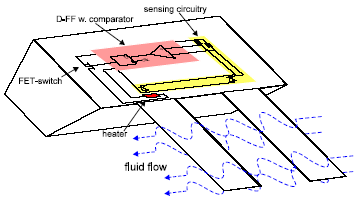
Fig. 5.20: The flow sensor with the circuitry.
In many microsystems and microelectronic circuits thermal effects have significant importance. Spatial distribution of the temperature on a chip should be simulated, together with electronic subsystem. The coupling is bidirectional, as electronics is influenced by the temperature, and electronic components represent heat sources.
Thermoelectrical simulation is performed in Alecsis using finite element (FE) method for spatial discretization. The user defines the geometry and placing of the components on the wafer by using commercial FE software with meshing capabilities. The strength of the method is in the fact that FE discretization can accurately describe the physical laws on irregular shapes with irregular mesh. The system of equations is extracted into the form applicable to analogue simulators. Afterwards, the electronic system or components described on higher level of abstraction are defined and coupled with thermal FE modules. Alecsis is employed to solve a system, assembled from particular element models previously programmed as libraries in AleC++.
The quality of the approach can be described on the flow sensor based on anemometry principle (system in Fig. 5.20, similar to [Jime98]). The heating resistor is employed for generating thermal gradient in the region of interest (wire, cantilever, bridge). The temperature difference between the referent and the heated position is proportional to the velocity of flow, since the flow disturbs the distribution of thermal gradients. It is a fluidic-thermal-electric system and requires simultaneous treatment of all participating physical domains.
Fig. 5.20: The flow sensor with the circuitry.
The placement of the components is shown in Fig. 5.20. It describes the circuitry for defining constant average temperature difference between the heater and the reference. The fluid influences the thermal flow, and that flow is measured by the temperature-dependant diodes.
Fig. 5.21: Main thermal flows in the flow sensor.
This system defines a sigma-delta converter of the first order with the low-pass feedback incorporated in the thermal system (Fig 5.21). The FET transistor is switched depending on the temperature difference between the heater and the reference. The frequency of the switching is a measure of the flow velocity.
Fig. 5.22: Temperature distribution on the chip.
The ANSYS v5.4 results for 2D thermal simulation with emphasized isotherms are shown in Fig. 5.22. Comparison with Alecsis results for the same thermal system shows relative error smaller than 0.002%. The 2D model was somewhat simplified. The bottom part of the structure in Fig. 5.22 has fixed temperature, which presumes the connection with an ideal sink. The system is modeled as adiabatic in z-plane, i.e. there is no heat transport in the direction of the z-axis.
Alecsis transient simulation results of the coupled electro-thermal system are shown in the Fig. 5.23. Traced signals are the heater temperature, the temperature of the cantilever close to the heater, the reference temperature, the measured fluid velocity, and the clock signal. Results show change of the frequency of the heat pulses with the change of the fluid flow velocity.
Fig. 5.23: Transient results for the behavior of the flow.
More details about electrothermal simulation in Alecsis can be found in [Jako99].